1.4.7. WORKING WITH LISTS
Example files that accompany this section: http://grasshopperprimer.com/appendix/A-2/1_gh-files.html
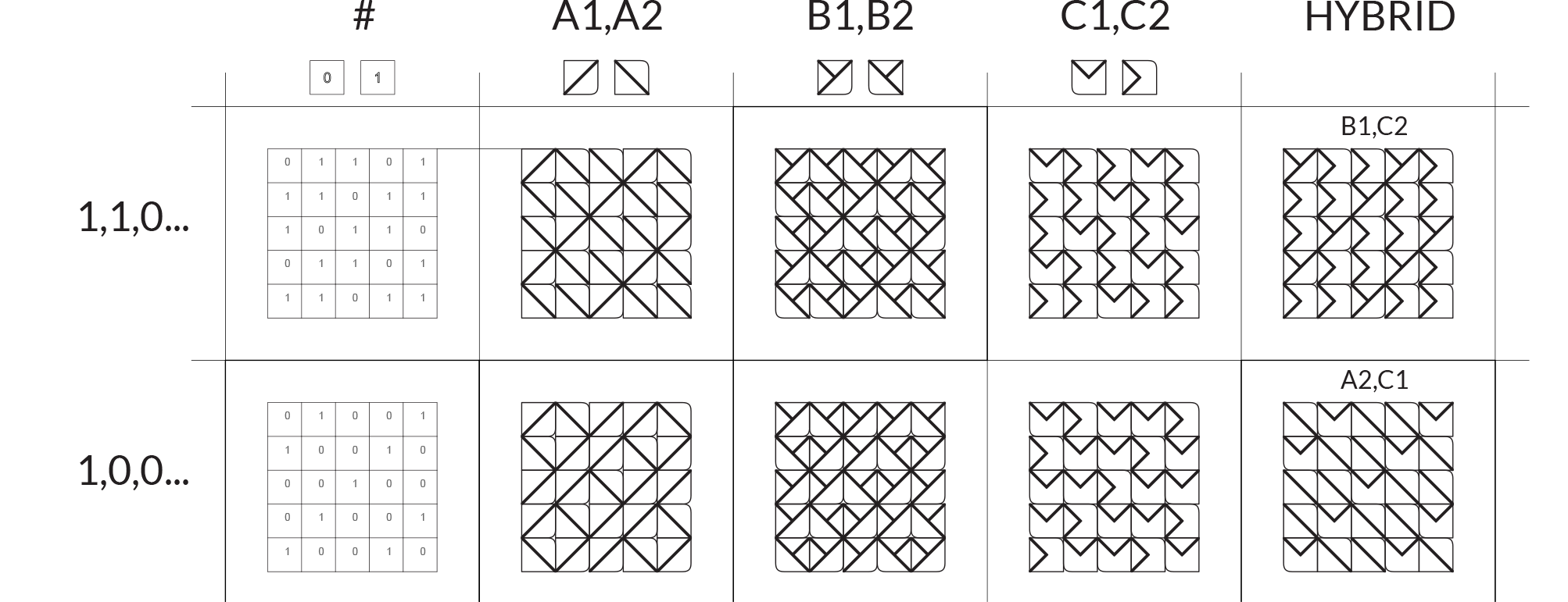
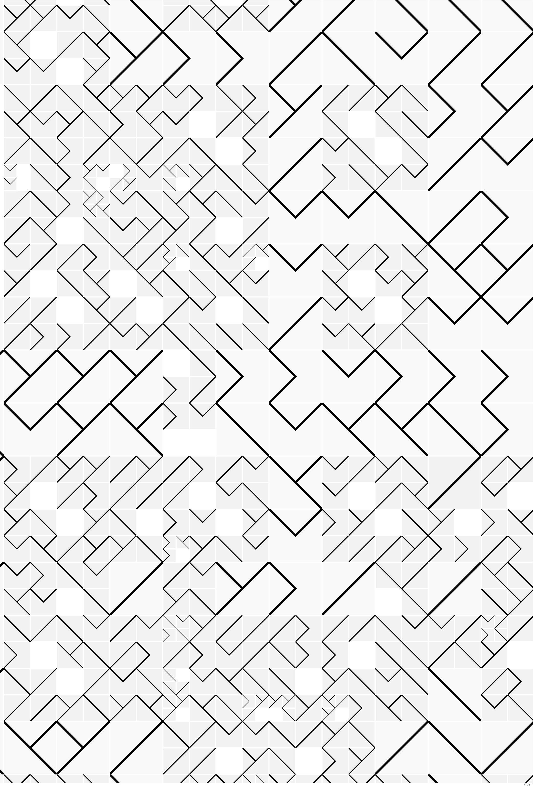
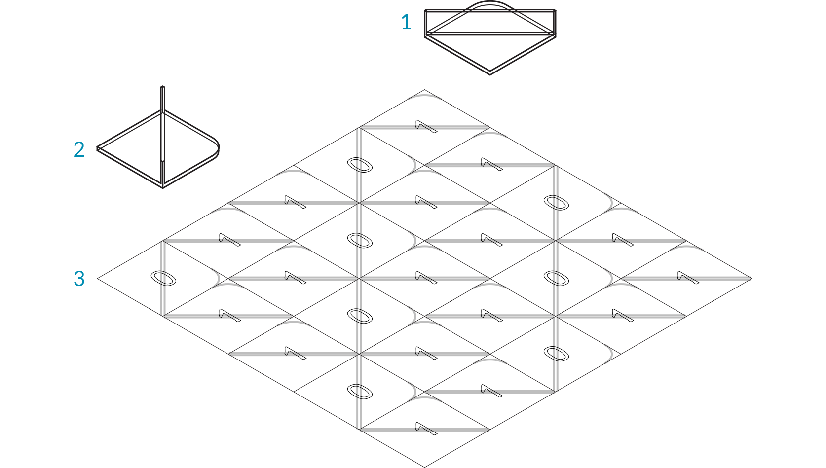
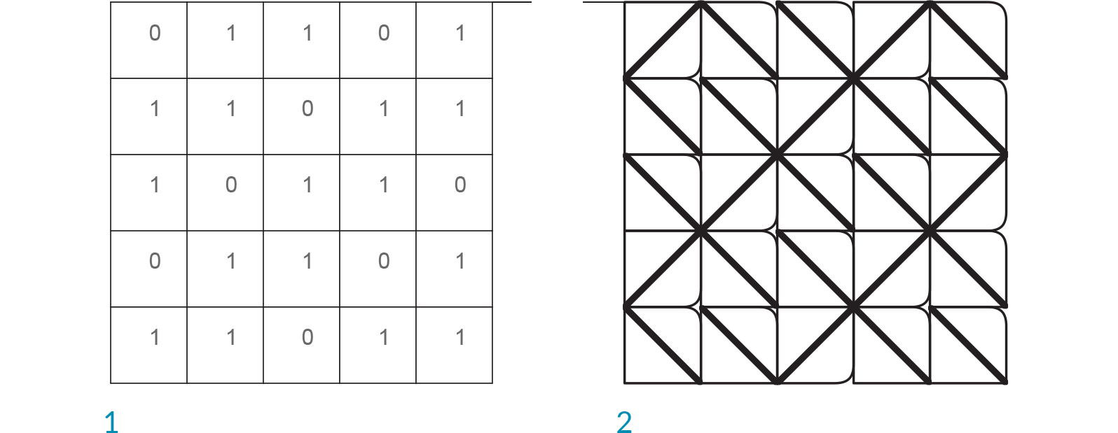
Lets take a look at an example using the components from the previous section. In this example, we are creating a tile pattern by mapping geometry to a rectangular grid. The pattern is created by using the List Item component to retrieve the desired tile from a list of geometry.
- Geometry corresponding to index 1
- Geometry corresponding to index 0
- Rectangular grid
- Mapping pattern
- Mapped geometry
| 01. | Start a Rhinoceros File. | |
| 02. | Create two equally sized squares. | |
| 03. | Create different geometries in each square.In the example shown above, we created a simple surface with a tab. The tab is filleted to demonstrate the orientation and the base is filleted to distinguish the two geometries. |
|
| 04. | Start a new definition, type Ctrl+N (in Grasshopper). | |
| 05. | Params/Geometry/Geometry – Drag and drop two Geometry parameters onto the canvas. |  |
| 06. | Right-Click the first Geometry Parameter and select set one Geometry. Set the first Geometry that you are referencing. | |
| 07. | Right-Click the second Geometry Parameter and select set one Geometry. Set the second Geometry that you are referencing. It is possible to reference multiple geometries in a single parameter, but for simplicity were are using two separate parameter components. |
|
| 08. | Params/Geometry/Curve – Drag and drop two Curve parameters onto the canvas. |  |
| 09. | Right-Click the first Curve Parameter and select set one Curve. Set the first square that you are referencing. | |
| 10. | Right-Click the second Curve Parameter and select set one Curve. Set the second square that you are referencing. Be sure that the geometry and the square that you are referencing correspond. |
|
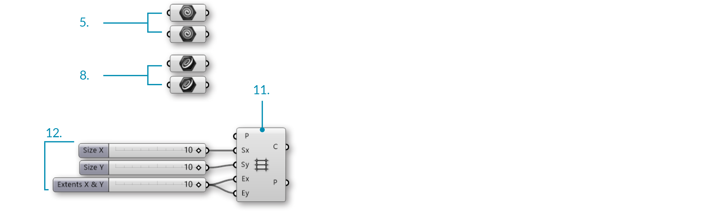
| 11. | Vector/Grid/Rectangular – Drag and drop a Rectangular Grid component onto the canvas. |  |
| 12. | Params/Input/Slider - Drag and drop three Number Sliders on the canvas. | |
| 13. | Double-click on the first Number Slider and set the following:
Lower Limit: 0 Upper Limit: 10 Value: 10 |
|
| 14. | Double-click on the second Number Slider and set the following:
Lower Limit: 0 Upper Limit: 10 Value: 10 |
|
| 15. | Double-click on the third Number Slider and set the following:
Rounding: Integers Lower Limit: 0 Upper Limit: 10 Value: 10 |
|
| 16. | Connect the first Number Slider to the Size X (Sx) input of the Rectangular Grid component. | |
| 17. | Connect the second Number Slider to the Size Y (Sy) input of the Rectangular Grid component. | |
| 18. | Connect the third Number Slider to the Extent X (Ex) input and the Extent Y (Ey) input of the Rectangular Grid component. |
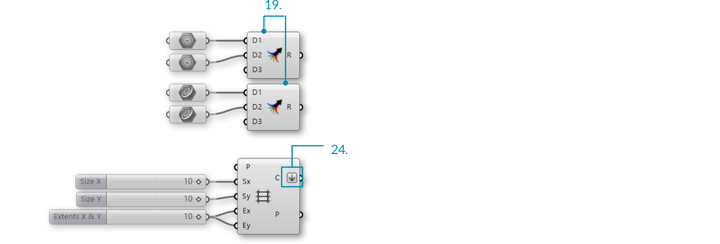
| 19. | Sets/Tree/Merge – Drag and drop two Merge components onto the canvas. |  |
| 20. | Connect the first Geometry parameter to Data Stream 1 (D1) input of the first Merge component. | |
| 21. | Connect the second Geometry parameter to Data Stream 2 (D2) input of the first Merge component. | |
| 22. | Connect the first Curve parameter to Data Stream 1 (D1) input of the second Merge component. | |
| 23. | Connect the second Curve parameter to Data Stream 1 (D2) input of the second Merge component. | |
| 24. | Right-click the Cells (C) output of the Rectangular Grid component and select Flatten. |
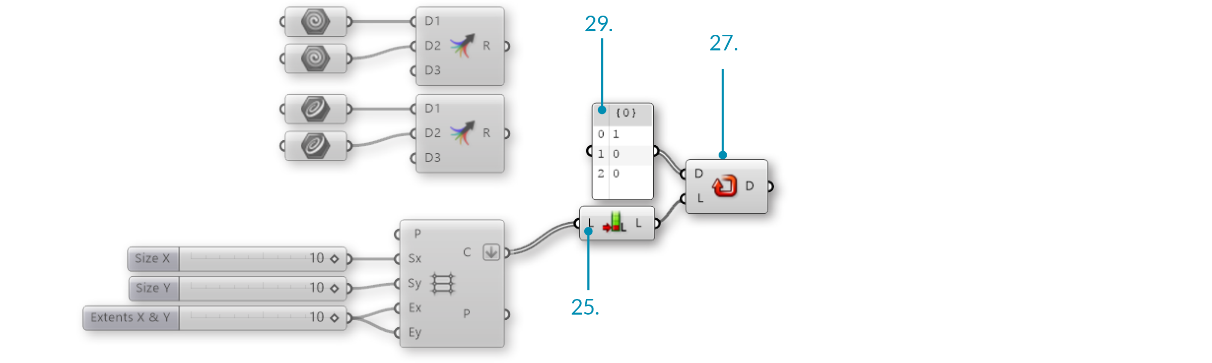
| 25. | Sets/List/List Length – Drag and drop a List Length component onto the canvas. |  |
| 26. | Connect the Cells (C) output of the Rectangular Grid component to the List (L) input of the List Length component. | |
| 27. | Sets/Sequence/Repeat Data – Drag and drop a Repeat Data component onto the canvas. |  |
| 28. | Connect the Length (L) output of the List Length component to the Length (L) input of the Repeat Data component. | |
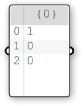
| 29. | Params/Input/Panel – Drag and drop a Panel onto the canvas. | |
| 30. | Double-click the Panel. Deselect multiline data, wrap items, and special codes. Enter the following:
0 0 This is the pattern in which the geometries are being distributed. 0 is calling out the first referenced Geometry and 1 is calling out the second referenced Geometry. Changing the number sequence will change the pattern, as will changing the extents of the grid. |
 |
| 31. | Connect the Panel to the Data (D) input of the Repeat Data component. |
| 32. | Sets/List/List Item – Drag and drop two List Item components. |  |
| 33. | Connect the Result (R) output of the first Merge component to the List (L) input of the first List Itemcomponent. | |
| 34. | Connect the Result (R) output of the second Merge component to the List (L) input of the second List Item component. | |
| 35. | Connect the Data (D) output of the Repeat Data component to the Index (i) input of the first and second List Item components. | |
| 36. | Transform/Affine/Rectangle Mapping – Drag and Drop the Rectangle Mapping component onto the canvas. |  |
| 37. | Connect the Cells (C) output of the Rectangular Grid component to the Target (T) input of the Rectangular Mapping component. | |
| 38. | Connect the items (I) output of the first List Item component to the Geometry (G) input of the Rectangular Mapping component. | |
| 39. | Connect the items (I) output of the second List Item component to the Source (S) input of the Rectangular Mapping component. |
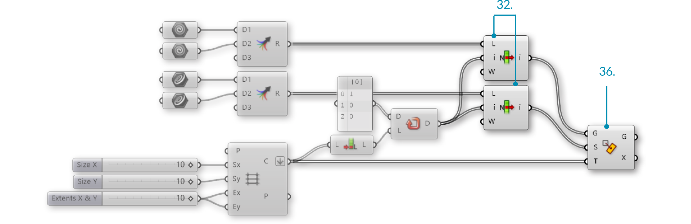
Changing the input geometry and the pattern will change the final tile pattern.